jacobs patch pipette blocks fluid flow|Perfusion of Patch Pipets : bespoke Many systems for rapid perfusion of isolated cells or membrane patches operate . Liquid growth media are used to recover bacteria immediately following the transformation step as well as to increase the number of bacteria from a colony or a glycerol .
{plog:ftitle_list}
Depending on the autoclave make & model, load probe & F0 capabilities may already be present or could be retrofit. However, depending on your application, you may not need (nor want) either of these features.
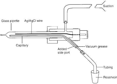
Many systems for rapid perfusion of isolated cells or membrane patches operate .Perfusion of Patch Pipets John M. Tang, E N. GZuandt, and R. S. Eisenberg 1. Introduction .The pipet perfusion method used here to control the internal solution in whole-cell patch-clamp .
To stop the fluid flow, clip the tube at the container’s side to block the fluid flow, then clip the tube at the suction side to stop the suction at the same time. This is the “stationary” control condition. . Place a patch pipette containing a 3 M KCl solution in the chamber to minimize the junction potential shift between the pipette .
Perfusion of Patch Pipets
2. Use the syringe linked to the filter and micro-loader tip to fill halfway a borosilicate pipette with intracellular solution. Tap the pipette a few times to eliminate any air bubbles that might be present in the tip of the pipette. 3. Place the glass pipette in the pipette holder. Place the pipette tip in the bath and focus the tip. 4.Use block fluid fast-flow active on. See above for details. Reduce aperture-maximum. See advice above. 7. Reduce the fluid bulk modulus. Note that reducing the fluid modulus will cause the fluid to be more deformable, so the fluid will have a smaller effect on the mechanical behavior than would be true in reality, and the volume balance (inflow . Patch-clamp and multi-electrode array electrophysiology techniques are used to measure dynamic functional properties of neurons. Whole-cell and cell-attached patch-clamp recordings in brain slices can be performed in voltage-clamp and current-clamp configuration to reveal cell-type-specific synaptic and cellular parameters governing neurotransmission.This block is transferred using a strip of hardened #50 ashless filter paper, blotted to remove excess fluid, and mounted on the chuck of the tissue slicer with cyanoacrylate glue. . It is recommended to make all patch pipettes at the beginning of the day (about 6-12 should suffice, depending on the experiment) but do not fill the pipettes .
Whether frictional effects need to be taken into account in a flowing fluid depends on many factors, some having to do with the properties of the fluid itself, others having to do with the geometrical properties of the pipe or channel confining the fluid, and still others relate to the rate of fluid flow and the type of flow.Like in other Simscape models, a series of connected fluid blocks create a network. Simscape Fluids blocks model one-dimensional flow and fluid flows in both directions along the network connection lines. Many Simscape Fluids blocks support reversed flows, which you can specify by using negative variables, such as negative mass flow rate. .
The development of today’s patch clamp technique is a result of the pioneering work of many scientists through the years. Seminal steps in the configuration of the technique were made between the late 70s and early 80s, when the high-resistance seal between the cell and a recording micro-pipette was developed [1, 2].This provided the basis for the whole-cell . Fill approximately 3/4 of a patch pipette with the internal solution, using the syringe with the microloader (Fig. 4). Place the pipette in the pipette holder, secure the micromanipulator to an appropriate starting position and apply positive pressure using a syringe or your mouth. 3.
(a) Experimental setup. The system consists of a conventional patch clamp rig equipped with a programmable 3-axis micromanipulator, a signal amplifier, a digital/analogue acquisition board, a computer and a custom-made electro-pneumatic actuator for controlling internal pressure of pipette. (b) Block diagram of the automated patch procedure. Undissolved clumps of PVP can block the perfusion system. Preheating saline and/or using stirring facilitate proper solvation thus help eliminate PVP clumping. . If cells in suspension are patched, the fluid flow from the canula can detach the cell from the patch pipette. Therefore, this protocol is best suited to test fluid shear dependent .
For single cell analysis, cytosolic indicator can be dialyzed with a patch pipette. Combined with a simultaneous filling of the cytosol with a polar high-affinity Ca 2+ indicator, this approach permits the simultaneous recording of cytosolic (Fluo-3, visible light) and ER derived signals (ratiometric Mag-Fura-2, UV-light) (d) Targeted-esterase . Initial Ca 2+ Entry. The first study on the cilium-dependent flow response established a requirement for Ca 2+ influx as one of the very early steps in the signaling mechanism ().Brief removal of extracellular Ca 2+ on the apical side of the epithelium was sufficient to make the cells completely nonresponsive to mechanical manipulation of the cilium . In all patch configurations (Fig. 3.2b–d), currents generated from the membrane patch can flow through either the recording pipette with a resistance of R p or leak out through the pipette/membrane junction with a resistance of R seal. Thus, the fraction of the current that will be recorded by the recording pipette will be
The patch clamp technique permits high-resolution recording of the ionic currents flowing through a cell's plasma membrane. In different configurations, this technique has allowed experimenters to .
Watch the Full Video at https://www.jove.com/v/58228/measurement-ion-concentration-unstirred-boundary-layer-with-open?utm_source=youtube&utm_medium=social_gl. Washing and refilling requires about 0.5 ml solution which is injected into the funnel by a pipette. The solution flow through the capillary depends on its diameter. . (a cell) is seated on the patch pipette, the perfusion system is moved by micromanipulator into the recording chamber and is positioned so that the cell (or patch) at the .Common pipette solutions used for whole-cell patch-clamp electrophysiology. The Patch Guide. . or experiments can use non-physiological pipette solutions to block or enhance the current flow through specific channels. . Cesium gluconate (Cs-Glu) internal solutions are used to block potassium channels to enhance synaptic currents (by raising .
This section summarizes materials required for patch-clamp recordings from rodent acute brain slices. 2.1 Extracellular Solutions. The extracellular solution used in the patch-clamp technique, “artificial” cerebrospinal fluid (ACSF), mimics the ionic composition of physiological extracellular cerebrospinal fluid (CSF).4. Once the pipette is in the bath, apply very light positive pressure through the pressure control system and hold the pressure in the pipette by closing the three-way valve. 5. Approach the coverslip by moving the micromanipulator and monitoring the pipette height on the screen. Always focus at or below the tip of the glass pipette. 6.Figure 10.3A illustrates an idealized experimental arrangement of an “outside-out” patch recording of a single ionotropic receptor. The patch pipette contains a solution with an ionic composition similar to that of the cytoplasm, whereas the solution exposed to the outer surface of the membrane has a composition similar to that of normal extracellular fluid. Patch clamp technique is one of the promising intracellular bio-electrical signal recording methods for measuring the electric current flowing through ion channels in a cell membrane [].It is well understood that the ion channels played important roles in regulating the flow of ions across the cell membrane, which are involved critically in various physiological .
Patch pipettes with a resistance of 2–3 . Fluid flow (5 ml/min) evoked ∼ . Direct block by bisindolylmaleimide of the voltage-dependent K + currents of rat mesenteric arterial smooth muscle. Eur. J. Pharmacol., 483 (2004), pp. 117-126. View PDF View article View in Scopus Google Scholar [12]
Equivalent circuit of the whole-cell configuration. The thin glass wall of the pipette provides capacitance (C p) that is nulled out after establishing a giga-ohm seal.This is parallel to the seal resistance (R seal), which results from the tight seal of the pipette glass and the cell membrane.Rupture of the patch results in a low resistance electrical connection with the cell .

As the diameter of the application pipettes varied in the 100–120 µm range, the flow rate was adjusted accordingly for the area of the tip of the application pipette to assure that the average velocity of the fluid would be ca. 400 cm/s at the tip of the application pipette. The calculation of the flow velocity was made assuming that, at a .Study with Quizlet and memorize flashcards containing terms like Ion channel behavior is sometimes called "stochastic." Which of the following best describes the meaning of this term?, Dr. Renko occasionally uses a patch clamp technique to study ion channels. Which of the following best describes this methodology?, What best completes the following statement? .Changes in junction potential between the Ag/AgCl reference electrode and bathing fluid were measured with an open pipette filled with 3 M KCl. Fluid flow could then shift the liquid/metal junction potential to approximately 7 mV. . we provide a method for measuring real ion concentrations in the unstirred boundary layer with an open patch .
large foot pedal autoclave
large horizontal autoclaves
A simple perfusion system for patch

I considered building a 55-gallon drum system, but finally decided to expand on my experience with transforming propane tanks into autoclaves. I wanted a vessel capable of holding both pressure and a vacuum, with the .
jacobs patch pipette blocks fluid flow|Perfusion of Patch Pipets